I am very happy with my Tevo Tarantula 3D printer! I have it up and running for about 6 weeks now. Let me tell you about my prints so far!

Reading all the forums, facebook groups, and of course the Tevo website, I decided on the way forward after finishing the build.
First, I would need to be able to print dimensionally reasonably accurate parts. In order to achieve that, I fist took a look at the extrusion. It is important that the extruder extrudes the commanded length of filament, to within a few percent. To check that, I fed in the filament for only a few centimeters. With that as "0", I measured 120mm from the infeed side of the extruder, and marked the filament with a black marker. Then, I commanded the extruder to feed 100mm into the teflon tube, and mesured how far from the extruder infeed side the mark ended up. That should be 20mm, of course, but in my case it was less than that. So I had to tune down my extruder a bit. As I measured 17mm, it had "over-extruded" 3mm, or 3 percent. So I dialed in 97% for my E-steps, and re-did the calibration sequence. And now it was OK! :)
Next thing to do is to measure if the displacement in X-, Y, and Z-direction is exactly as commanded. Most people use a 20x20x20mm calibration cube for that purpose, but I decided to use the calibration cat I found on thingiverse: https://www.thingiverse.com/thing:1545913. A similar procedure here: print the cat, and measure in all directions. If a 20mm side prints as 20.2mm, you know you have to reduce your "steps" in that direction by 1%.

With that dialed in, the first thing to print was a fan duct, so that I could cool down the molten filament as soon as possible after it leaves the nozzle. Remarkably, Tevo elected not to provide product cooling in the kit
I decided on the dual fan dan duct https://www.thingiverse.com/thing:1850163
Waiting for the fans to arrive I alredy printed a lego brick I nedded for my LEGO quadcopter, form Thingiverse too: https://www.thingiverse.com/thing:2411971. I needed 4, but I left it at this one for now, just to prove to myself that I could do it.

Next on the list was Christmas Cards (3D printed puzzle), because it was that time of the year ;)
I was surprised to see that the puzzels actually assembled quite stirdily. Even a bit hard to slide the pieces in their slots. But it all did work, right off the print bed. All I had to do was change the text to say happy 2018, instead of 2017. 😄


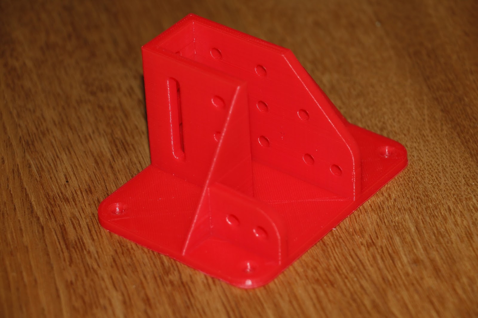
Then, I started printing the stiffening brackets for Tevo Tarantula in red, because I had a new 1 kg spool of red PLA. I wanted all brackets to be the same colour, and the filament I got shipped with the printer was of the colour changing PLA type - both rolls.
Half way during the printing of the brackets, I came across a so called Temperature Tower: https://www.thingiverse.com/thing:2722610. This allows you to print layers at different temperatures, if you manually edit the generated G-code. Editing is easy, as G-code is plain ASCII text. Just search for the label ";layer:##", with ## being 0, 50, 100, 150, etc., and add the approriate G-code to set a net hot-end temperature (M104 S###) on a new line.

After printing, you can judge the effect of nozzle temperature on the print quality. In the case of this red PLA, the optimum nozzle temperature was 205°C. This resulted in the best surface quality, and overhang capability. Overhangs were still very poor at pretty much every temperature, without product cooling, but at that temperature, things were the best I could get. So I altered the standard printing temperature of the material in Cura to 205°C
I soon noticed that for larger prints, a spool holder would be needed. Manual guiding the filament is nice if you sit next to the printer anyway. But any print of a bit of significant volume takes hours to print, and then you'd want to leave for a minute ;)
I ended up printing three spool holders., because the first two did not live up to my expectations.
The PrintrBot Spool Holder was meant to go on top of a printer, and I was gonna place it on the table, in front of the printer. So it feeds the filament upwards. I did not think the "eye" would be a problem, but it proved to be. The filament got caught in the gap between the two halves of the eye, pulling the entire spool holder up to the extruder. I solved it temporarily with some tape, but that was not a permanent solution.
Next, I tried the RCLifeOn spool holder. That proved to be a wrong solution for a not-so-stiff frame, hanging a 1 kg roll of filament from one of the vertical extrusion profiles. Plus, the dynamics of all those Y movements caused the frame to wobble back and forth during the print. Not a desireable situation!
In the end this remake of TUSH (The Ultimate Spool Holder), TUSH++: https://www.thingiverse.com/thing:2451368 became my spool holder of choice. Once I get around to mounting the brackets to the frame, I will also screw the two bottom strips to the table. I will still have the possibility to take narrower and wider spools (the ones that came with the printer are narrower than the 1 kg filament roll).

So now I could print the remainder of the brackets without having to constantly sit next to the printer. I had gained enough confidence by now that the electronics were connected well enough not to melt.
And with one of the larger brackets predicting to take 4.5 hrs to print, that is pretty welcome :)

While sitting next to the printer, looking at the whole printing process, I noticed that I needed some more light. I would grab the LED flaslight from the kitchen to shine on the print from various angles to see how the surface texture would develop, or if there were any defects, or something.
I also knew I had some WS2812B RGB LED strips laying around, waitng to be affixed to one of my drones. But since I bought 10 of them at the time, I also knew I had some spares. Thing is, with these LED strips, that they need an Arduino board or something like that to send out a control signal to the signal pin. It does not work if you think to just put full power on to the + and -, because when there is no signal on the signal pin, all LEDs remain unlit. So I looked on Thingiverse again to see if I could fins a suitbale enclosure for an Arduino Nano, together with a buck convertor (12V to 5V convertor). The latter is needed to power the Arduino, and to power the LED strips, because I could fit 4 strips with 8 LED, with 3 colours per LED, which can draw 20mA max. That comes down to 4x8x3x20=1.920 mA = almost 2Amps! That is definitely too much to drive through an Arduino, so the Arduino only delivers the control signal. And since it is Arduino controlled, I can not only set the colour (which I want to be bright white in this case), but I can also have it ramp up slowly, so that the 2A are not drawn instantaneously from the power supply.
Ok, back to the housing. I found a parametric Universal Box, desined in openSCAD by this guy callled Heartman, on Thingiverse again: https://www.thingiverse.com/thing:1264391. Which, of course, meant I would have to install OpenSCAD, if I wanted to modify the box' dimensions...
OpenSCAD is not very difficult to grasp, especially with a nicely comeented design, such as this one. The left window contains the geometry in a sort of programming language. Somewhere down the line, there are parameters that define things like legth, width, height, ventilation slots yes/no, PCB feet yes/no, and all sorts of hole types for one of the end plates (for dials, gauges, displays). Very neat! Especially all those possibilities with the front plate made this a design I wanted to store and re-use in the furture!

In this case, I did want ventilation slots, so I left that parameter at 1. I did not want PCB feet (planned on mounting both PCBs to one half of the box each, with thick double-sided tape), so the top half and the bottom half are the same shape. And I wanted only one rectangular hole to mount a rocker switch, and a smaller hole to feed the wires trough in one of the end plates.
After printing, the holes in the lugs did not line up exactly with the holes in the wall of the opposite box-half, so it would be difficult to put screws through there. For now, not so much a problem, because I intended to fix the box to the printer with tie-wraps anyway - at least until I got the brackets mounted to the printer frame. I'll probably print a new box once I've got the brackets in place, and gone through the whole calibration process once more. I expect (or at least hope) to be able to print true, dimensionally correct parts, then... And maybe I'll integrate something to attach the box with T-nuts, or somethng. We'll see!

By now, the fans have arrived. I immediately mounted the green fan duct. I did not do wire management just yet, because the printer will need to be mostly disassembled anyway. Right away printed a calicat, and a fan duct in red, to be mounted together with the brackets once I get around to that (ordered some extra T-nuts and bolts; still waiting for them to arrive)


I think the difference is staggering! On the left the latest calicat without product cooling (yellowish green), on the right my first one WITH product cooling (Red). Obviously, the 45 degree overhang is not a problem anymore. The same goes for bridging a small gap (will have to go find out what the limits are on that one), although that does not show in these pictures very well. Also, the surface quality has improved, along with the straightness, and the sharpness of the corners. Because the bridging performance is better, calicat now has a closed top surface, where before product cooling there were always 3 or 4 spots where there either was a hole, or only a verry thin, see-through top layer. So all in all very happy with what a difference this cooling makes!
Meanwhile, together with the fans, I also ordered a roll of white PLA. I had read about, and planned to make myself, some lithophanes. That are flat panes (can also be cylindrical) on which a grayscale picture is printed with the thicknes varying according the the darkness of the picture. That way, if it is back-lit, you see the picture shining through, much linke a lamp shade with a print on it.
With my new filament I first printed another temperature tower. It became immediately clear that the "brim" did not attach to the bed properly, but I decided to let the print run anyway, and see where it would end. Well, alfter a couple of temperature decreases, the print came loose from the bed, so I stopped it. But I still could judge the optimum temperature to be 205°C as well.

After that, another calicat, to see if any of the X-, Y-, Z-steps needed to be re-calibrated.
Dimensions were different from the red calicat at the same settings, but I decided to leave it as is, and print my first lithophane. This was the longest print so far, with 5 hours and 20 minutes. And that for a 75x75x4mm print... But it was at 0.1mm layer height, I must admit. That means 750 layers, and that takes some time :)

There is still some stringing, and the bottom side of the top "frame" bar is not so nice. That is because the distance is too far to bridge. I need to make sure the next one is not entirely white accross the full top of the picture.

The springs in the battery compartment of my wireless remote control of my DSLR were corroded. And now, while trying to put fresh batteries in, one of them snapped. Naturally, I now decided I would make a new battery case, to fit a 1S LiPo stick (I have about 10 of those laying around doing nothing) instead of the two AAA batteries I keep having to replace.
But hat would mean I would need to do some designing. So I downloaded and installed Fusion 360 from Autodesk. As a student, or educator (I happen to be both, at this time) this software is free. Otherwise, a standard license costs $300,=/year.
So I measured the existing part it would have to mate with as best I could, and also the battery - and decided on it's position. I chose not to make a battery hatch, but keep it a simple screw-on box. That means I would have to unscrew the cover to get the battery out to recharge it. But for a first ever functional piece, I thought that was complex enough.

The first print revealed that I had made a small error in measuring the radius at the front, and therewith the width of the box at that end, so it would not close properly. But now I did have a physical model in my hand, of which I now could measure how much I would need to correct those values.
Second print fitted almost perfectly, but during assembly, one of the pylons broke off. So I decided on a thicker wall for the pylons, add fillets all around, and create a pocket for the battery (the thicker walls interfered with the width of the battery).
Third print was perfect!

So in the end, it had cost me about 4 hours of playing around with Fusion 360, Three one-hour prints, about 10 m, or 33 grams of filament (~€ 0.73), and some electricity (200Wx3hr = 0.6kWh ~ € 0.13). So at the cost of less than €1,=, and some time spent on a hobby, I now can make remotely triggered photographs again, and I do not have to worry about running out of batteries to power the thing anymore 😃.
But most of all: I now feel the satisfaction of designing from scratch, and actually producing functional parts!
Future plans with this printer include a full lithophane LED lamp, including base, top, lighting, and of course ... lithophanes! More RC related, I will probably be printing brackets and mounts for cameras ("FPV" and "action"). I even have plans for an FPV canopee for my Durafly Tundra, with room for a head tracking servo, and a place to affix all the electronics involved, like a BEC, Video Transmitter, and antenna. I may even venture out on the path of 3D printng an airplane...
Stay tuned for more! (subscribe in the menu top-right ;) )
Disclaimer (see also the disclaimer page in the top menu):
This printer was given to me by GearBest for review. So indeed, I did not pay for it. Nevertheless, I treat is as if I bought it, and use it like I otherwise would too. The only requirement GearBest gave me was that I write a review on it, which I already did. See my build article to see what I likedd and didn't like about the kit, putting it together.
Would you like to own this printer too? It is available through this affiliate link: Tevo Tarantula. Clicking the link will support me and this blog, especially if you decide to buy something from GearBest.
Currently (end of January 2018), there is a Flash Sale for the "large bed" (200x280x200) version of this printer, which will reduce the price to € 188.32. From time to time, there are also codes available that could reduce the price even further. Please contact me through the contact form top-right to check for the latest deals.
There are also versions with auto bed leveling, and/or dual extruders (for printing two colours in a single layer of the model), aside from the two bed sizes. Any combination of the three variables is possible!
If you are really interested in purchasing a printer, but there is no code available at the moment, I might be able to arrange a personal code for you. Again: ask me throught he contact form of this blog, and I will see what I can arrange for you.
For the basic version, expect a price point around €150, I might even get you a better deal.
Of course, there are lots of other printers to chooes from too. Each with their own stregths, and price points: GearBest 3D Printers, but this Tevo Tarantula, I found to have a really nice sweet spot between features and price. For hthis kit, you need to be a tinkerer, though. See my build article for some of the challenges you might face during the build.
Another great resource for deals on GearBest is the facebook page NoHuries: https://www.facebook.com/NoHurries/

Reading all the forums, facebook groups, and of course the Tevo website, I decided on the way forward after finishing the build.
First, I would need to be able to print dimensionally reasonably accurate parts. In order to achieve that, I fist took a look at the extrusion. It is important that the extruder extrudes the commanded length of filament, to within a few percent. To check that, I fed in the filament for only a few centimeters. With that as "0", I measured 120mm from the infeed side of the extruder, and marked the filament with a black marker. Then, I commanded the extruder to feed 100mm into the teflon tube, and mesured how far from the extruder infeed side the mark ended up. That should be 20mm, of course, but in my case it was less than that. So I had to tune down my extruder a bit. As I measured 17mm, it had "over-extruded" 3mm, or 3 percent. So I dialed in 97% for my E-steps, and re-did the calibration sequence. And now it was OK! :)
Next thing to do is to measure if the displacement in X-, Y, and Z-direction is exactly as commanded. Most people use a 20x20x20mm calibration cube for that purpose, but I decided to use the calibration cat I found on thingiverse: https://www.thingiverse.com/thing:1545913. A similar procedure here: print the cat, and measure in all directions. If a 20mm side prints as 20.2mm, you know you have to reduce your "steps" in that direction by 1%.

With that dialed in, the first thing to print was a fan duct, so that I could cool down the molten filament as soon as possible after it leaves the nozzle. Remarkably, Tevo elected not to provide product cooling in the kit
I decided on the dual fan dan duct https://www.thingiverse.com/thing:1850163
Waiting for the fans to arrive I alredy printed a lego brick I nedded for my LEGO quadcopter, form Thingiverse too: https://www.thingiverse.com/thing:2411971. I needed 4, but I left it at this one for now, just to prove to myself that I could do it.

(on here are also the other three I printed later, as you can see from the colour)
Next on the list was Christmas Cards (3D printed puzzle), because it was that time of the year ;)
I was surprised to see that the puzzels actually assembled quite stirdily. Even a bit hard to slide the pieces in their slots. But it all did work, right off the print bed. All I had to do was change the text to say happy 2018, instead of 2017. 😄


Then, I started printing the stiffening brackets for Tevo Tarantula in red, because I had a new 1 kg spool of red PLA. I wanted all brackets to be the same colour, and the filament I got shipped with the printer was of the colour changing PLA type - both rolls.
Half way during the printing of the brackets, I came across a so called Temperature Tower: https://www.thingiverse.com/thing:2722610. This allows you to print layers at different temperatures, if you manually edit the generated G-code. Editing is easy, as G-code is plain ASCII text. Just search for the label ";layer:##", with ## being 0, 50, 100, 150, etc., and add the approriate G-code to set a net hot-end temperature (M104 S###) on a new line.

After printing, you can judge the effect of nozzle temperature on the print quality. In the case of this red PLA, the optimum nozzle temperature was 205°C. This resulted in the best surface quality, and overhang capability. Overhangs were still very poor at pretty much every temperature, without product cooling, but at that temperature, things were the best I could get. So I altered the standard printing temperature of the material in Cura to 205°C
I soon noticed that for larger prints, a spool holder would be needed. Manual guiding the filament is nice if you sit next to the printer anyway. But any print of a bit of significant volume takes hours to print, and then you'd want to leave for a minute ;)
I ended up printing three spool holders., because the first two did not live up to my expectations.
The PrintrBot Spool Holder was meant to go on top of a printer, and I was gonna place it on the table, in front of the printer. So it feeds the filament upwards. I did not think the "eye" would be a problem, but it proved to be. The filament got caught in the gap between the two halves of the eye, pulling the entire spool holder up to the extruder. I solved it temporarily with some tape, but that was not a permanent solution.
Next, I tried the RCLifeOn spool holder. That proved to be a wrong solution for a not-so-stiff frame, hanging a 1 kg roll of filament from one of the vertical extrusion profiles. Plus, the dynamics of all those Y movements caused the frame to wobble back and forth during the print. Not a desireable situation!
In the end this remake of TUSH (The Ultimate Spool Holder), TUSH++: https://www.thingiverse.com/thing:2451368 became my spool holder of choice. Once I get around to mounting the brackets to the frame, I will also screw the two bottom strips to the table. I will still have the possibility to take narrower and wider spools (the ones that came with the printer are narrower than the 1 kg filament roll).

So now I could print the remainder of the brackets without having to constantly sit next to the printer. I had gained enough confidence by now that the electronics were connected well enough not to melt.
And with one of the larger brackets predicting to take 4.5 hrs to print, that is pretty welcome :)
While sitting next to the printer, looking at the whole printing process, I noticed that I needed some more light. I would grab the LED flaslight from the kitchen to shine on the print from various angles to see how the surface texture would develop, or if there were any defects, or something.
I also knew I had some WS2812B RGB LED strips laying around, waitng to be affixed to one of my drones. But since I bought 10 of them at the time, I also knew I had some spares. Thing is, with these LED strips, that they need an Arduino board or something like that to send out a control signal to the signal pin. It does not work if you think to just put full power on to the + and -, because when there is no signal on the signal pin, all LEDs remain unlit. So I looked on Thingiverse again to see if I could fins a suitbale enclosure for an Arduino Nano, together with a buck convertor (12V to 5V convertor). The latter is needed to power the Arduino, and to power the LED strips, because I could fit 4 strips with 8 LED, with 3 colours per LED, which can draw 20mA max. That comes down to 4x8x3x20=1.920 mA = almost 2Amps! That is definitely too much to drive through an Arduino, so the Arduino only delivers the control signal. And since it is Arduino controlled, I can not only set the colour (which I want to be bright white in this case), but I can also have it ramp up slowly, so that the 2A are not drawn instantaneously from the power supply.
Ok, back to the housing. I found a parametric Universal Box, desined in openSCAD by this guy callled Heartman, on Thingiverse again: https://www.thingiverse.com/thing:1264391. Which, of course, meant I would have to install OpenSCAD, if I wanted to modify the box' dimensions...
OpenSCAD is not very difficult to grasp, especially with a nicely comeented design, such as this one. The left window contains the geometry in a sort of programming language. Somewhere down the line, there are parameters that define things like legth, width, height, ventilation slots yes/no, PCB feet yes/no, and all sorts of hole types for one of the end plates (for dials, gauges, displays). Very neat! Especially all those possibilities with the front plate made this a design I wanted to store and re-use in the furture!

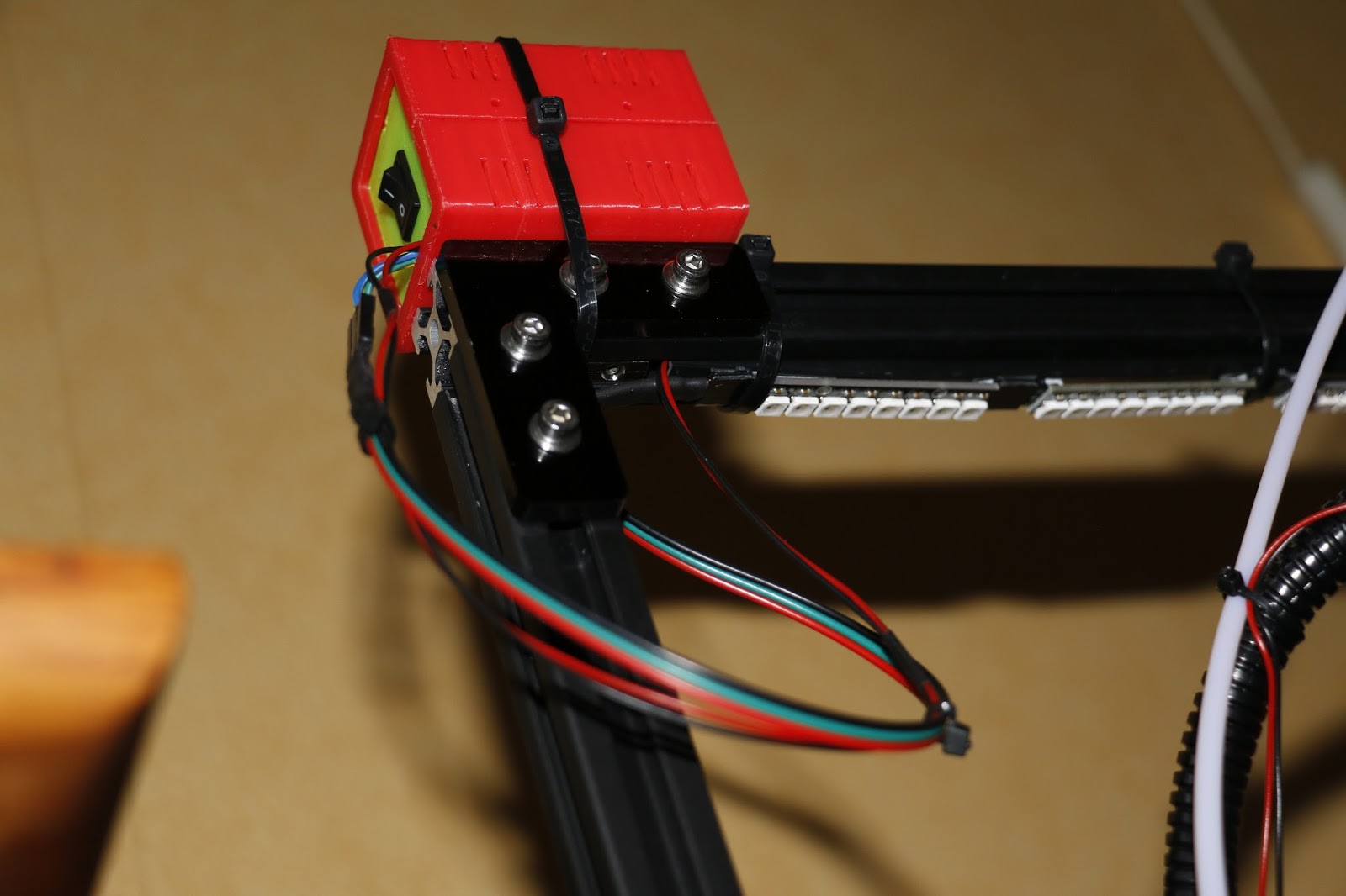
In this case, I did want ventilation slots, so I left that parameter at 1. I did not want PCB feet (planned on mounting both PCBs to one half of the box each, with thick double-sided tape), so the top half and the bottom half are the same shape. And I wanted only one rectangular hole to mount a rocker switch, and a smaller hole to feed the wires trough in one of the end plates.
After printing, the holes in the lugs did not line up exactly with the holes in the wall of the opposite box-half, so it would be difficult to put screws through there. For now, not so much a problem, because I intended to fix the box to the printer with tie-wraps anyway - at least until I got the brackets mounted to the printer frame. I'll probably print a new box once I've got the brackets in place, and gone through the whole calibration process once more. I expect (or at least hope) to be able to print true, dimensionally correct parts, then... And maybe I'll integrate something to attach the box with T-nuts, or somethng. We'll see!
By now, the fans have arrived. I immediately mounted the green fan duct. I did not do wire management just yet, because the printer will need to be mostly disassembled anyway. Right away printed a calicat, and a fan duct in red, to be mounted together with the brackets once I get around to that (ordered some extra T-nuts and bolts; still waiting for them to arrive)


Meanwhile, together with the fans, I also ordered a roll of white PLA. I had read about, and planned to make myself, some lithophanes. That are flat panes (can also be cylindrical) on which a grayscale picture is printed with the thicknes varying according the the darkness of the picture. That way, if it is back-lit, you see the picture shining through, much linke a lamp shade with a print on it.
With my new filament I first printed another temperature tower. It became immediately clear that the "brim" did not attach to the bed properly, but I decided to let the print run anyway, and see where it would end. Well, alfter a couple of temperature decreases, the print came loose from the bed, so I stopped it. But I still could judge the optimum temperature to be 205°C as well.

After that, another calicat, to see if any of the X-, Y-, Z-steps needed to be re-calibrated.
Dimensions were different from the red calicat at the same settings, but I decided to leave it as is, and print my first lithophane. This was the longest print so far, with 5 hours and 20 minutes. And that for a 75x75x4mm print... But it was at 0.1mm layer height, I must admit. That means 750 layers, and that takes some time :)

There is still some stringing, and the bottom side of the top "frame" bar is not so nice. That is because the distance is too far to bridge. I need to make sure the next one is not entirely white accross the full top of the picture.

The springs in the battery compartment of my wireless remote control of my DSLR were corroded. And now, while trying to put fresh batteries in, one of them snapped. Naturally, I now decided I would make a new battery case, to fit a 1S LiPo stick (I have about 10 of those laying around doing nothing) instead of the two AAA batteries I keep having to replace.
But hat would mean I would need to do some designing. So I downloaded and installed Fusion 360 from Autodesk. As a student, or educator (I happen to be both, at this time) this software is free. Otherwise, a standard license costs $300,=/year.
So I measured the existing part it would have to mate with as best I could, and also the battery - and decided on it's position. I chose not to make a battery hatch, but keep it a simple screw-on box. That means I would have to unscrew the cover to get the battery out to recharge it. But for a first ever functional piece, I thought that was complex enough.

The first print revealed that I had made a small error in measuring the radius at the front, and therewith the width of the box at that end, so it would not close properly. But now I did have a physical model in my hand, of which I now could measure how much I would need to correct those values.
Second print fitted almost perfectly, but during assembly, one of the pylons broke off. So I decided on a thicker wall for the pylons, add fillets all around, and create a pocket for the battery (the thicker walls interfered with the width of the battery).
Third print was perfect!

So in the end, it had cost me about 4 hours of playing around with Fusion 360, Three one-hour prints, about 10 m, or 33 grams of filament (~€ 0.73), and some electricity (200Wx3hr = 0.6kWh ~ € 0.13). So at the cost of less than €1,=, and some time spent on a hobby, I now can make remotely triggered photographs again, and I do not have to worry about running out of batteries to power the thing anymore 😃.
But most of all: I now feel the satisfaction of designing from scratch, and actually producing functional parts!
Future plans with this printer include a full lithophane LED lamp, including base, top, lighting, and of course ... lithophanes! More RC related, I will probably be printing brackets and mounts for cameras ("FPV" and "action"). I even have plans for an FPV canopee for my Durafly Tundra, with room for a head tracking servo, and a place to affix all the electronics involved, like a BEC, Video Transmitter, and antenna. I may even venture out on the path of 3D printng an airplane...
Stay tuned for more! (subscribe in the menu top-right ;) )
Disclaimer (see also the disclaimer page in the top menu):
This printer was given to me by GearBest for review. So indeed, I did not pay for it. Nevertheless, I treat is as if I bought it, and use it like I otherwise would too. The only requirement GearBest gave me was that I write a review on it, which I already did. See my build article to see what I likedd and didn't like about the kit, putting it together.
Would you like to own this printer too? It is available through this affiliate link: Tevo Tarantula. Clicking the link will support me and this blog, especially if you decide to buy something from GearBest.
Currently (end of January 2018), there is a Flash Sale for the "large bed" (200x280x200) version of this printer, which will reduce the price to € 188.32. From time to time, there are also codes available that could reduce the price even further. Please contact me through the contact form top-right to check for the latest deals.
There are also versions with auto bed leveling, and/or dual extruders (for printing two colours in a single layer of the model), aside from the two bed sizes. Any combination of the three variables is possible!
If you are really interested in purchasing a printer, but there is no code available at the moment, I might be able to arrange a personal code for you. Again: ask me throught he contact form of this blog, and I will see what I can arrange for you.
For the basic version, expect a price point around €150, I might even get you a better deal.
Of course, there are lots of other printers to chooes from too. Each with their own stregths, and price points: GearBest 3D Printers, but this Tevo Tarantula, I found to have a really nice sweet spot between features and price. For hthis kit, you need to be a tinkerer, though. See my build article for some of the challenges you might face during the build.
Another great resource for deals on GearBest is the facebook page NoHuries: https://www.facebook.com/NoHurries/
This comment has been removed by a blog administrator.
ReplyDelete